About Me

Pilani, Rajasthan, India
I am an engineering student currently pursuing an undergraduate degree in Electronics & Instrumentation from BITS Pilani, Pilani campus. My hobbies are reading novels- fiction and non-fiction alike, playing and watching football, dabbling with new software and going through blogs. I love reading Electronics For You. It has helped me a lot in my college life. And sometimes, people around me.

Hope you find this blog useful. Thank you.

Wednesday, July 27, 2011

Serial Communication on ATmega32/16


Hello all. In this post, I will be covering a very basic introduction to RS232 based serial communication on ATmega32/16 using the USART hardware. But before you start reading, let me warn you – this post is a bit lengthy (but contains everything you need as a beginner...so no skipping :P), so bear with it. Secondly, please keep a datasheet of ATmega32 ready with you, this is the link.

The Basics

I want to talk to my friend. I use my vocal cords (hardware) to transmit meaningful information (software - analogy) but using the rules of language to do it, so that he can understand it. So generalizing, for any form of communication to take place, you need hardware, software and some rules that govern the communication, right?
In the opening statement to this post, I referred to three terms which are very important to understand. Most of the time, there is always a confusion regarding this terms and it is desirable to know the difference. Amongst various advantages, it helps the show-off factor.
First of all, serial communication is the form of communication in which data is sent – one bit at a time - across a communication channel. The other option is parallel communication, in which, many bits are sent simultaneously across the communication channel. Needless to say, parallel communication is faster than serial communication and also easier to fathom. But a major disadvantage is the cabling cost, which is a very important factor in the transition from parallel to serial communication over the years.

RS232 (RS = Recommended Standard) is a protocol – a set of standards/rules – using which control signals are sent to and from the transmitter and receiver used for serial communication. In very simple words, RS232 is a set of rules by which you can perform serial communication. That 9-pin male socket at the back of your desktop’s CPU is a serial port that carries out communication using RS232, when in use.

USART (Universal Synchronous and Asynchronous Receiver and Transmitter) is hardware – an integrated circuit – most of the times, that helps accomplish serial communication. USART is present inside the microcontroller – begging you to use it.
So, we know what the hardware, software and the rules are – now what?

Serial Communication – why should I care?

Serial communication is the basis of a lot of communication going around you. The communication inside your cell-phone, those noisy printers at the medicine stores, Distributed Control Systems in industries, MP3 players amongst many other systems. The protocols used vary from RS232, RS485, I2C, SPI, Token-passing etc.
As for techfest aspirants, those IP-based events in which you perform image processing on some software (Matlab, OpenCV, Scilab etc.) and are supposed to control your robot using the results of the same – involve serial communication. Yes – you CAN use parallel communication but that not only increases the hardware but also makes it necessary to have a desktop computer. What college kid uses a desktop?! :P
Apart from this, you can make a lot of projects based on this in various project competitions. So, hope you read on – with a purpose.

RS232 – information you should know

So we all agree that the set of rules used is the most important thing when you want to communicate with someone. If there are no rules, there would be no communication!
You will read on a number of sites that it supports both synchronous and asynchronous modes.   

Synchronous serial communication is that type of serial communication in which you supply a constant external clock and all the bits are transmitted with respect to this clock. The clock is analogous to a musical beat of any instrument, say drums. You must have noticed, in songs there is generally a beat going on and the words/lyrics start only at particular beats. Different instruments kick in, words stop and all types of such events take place at particular beats making the song memorable. Similar is the case with synchronous serial communication.

Asynchronous serial communication is that type of serial communication in which there is no need of an external clock. Immediately, the question comes to mind – how do I differentiate between messages? The answer is – with the help of start and stop bits. These bits are preset sequences of electronic signals that signify the start or stop of a meaningful message. In very simple terms, an asynchronous data-packet is like your data-bits enclosed in an envelope of start and stop bits. Hence just like content inside one envelope can’t affect the content inside another, the data inside one data-packet is separated from that in the other.
Also, a very important thing to know about RS232 is the logic level. In this protocol, a logical ‘1’ is signified by -3 to -15 volts and a logical ‘0’ by +3 to +15 volts (yes – it is NOT a typo, the logic is inverted). Hence, when establishing a connection between your computer and microcontroller, a logic-level shifter is needed to convert the TTL logic of your mu-c to the above-mentioned logic.

The Circuitry

The IC generally used for the logic shifting purpose is MAX232. It is quite cheap and almost universally used for this purpose. Refer to the following schematic for the circuit connections. Please note: in the 9 pins present on the serial connector, only three pins – RX, TX and GND are needed for most beginner applications. Refer to the pinout diagram of 9 pin male connector to identify the pins to be used.
Circuit Schematic
RS232 connector - male Pinout (9-pin)

Initialization of USART - theory

You have some knowledge about RS232. You have your circuit ready. Now how to make USART work?
USART has to be initialized first. Initialization is important to let the microcontroller know as to what conditions it has to work under. For beginner-level applications, initialization involves specifying the Baud Rate, setting the Frame Format, enabling the Transmitter/Receiver depending on the application and lastly, selecting the mode of operation – synchronous or asynchronous.

Baud Rate is the speed of your communication and is measured in bits per second. At this stage, you need not worry too much about the baud rate and how to set the correct clock frequency to get 0% error. I will discuss that in a future post.

Frame Format refers to how you want your data packet to look. How many start bits do you want? How many stop bits? How many data bits? Do you want a parity bit (need not bother about this now). We will focus only on selecting the data bits.

Initialization is done by writing ‘1’ or ‘0’ to particular bits of special registers meant for USART. This section 
covered only the theory. Scroll down for the code and register details. But if you are a beginner, I suggest you read this post sequentially.

Sending and Receiving data – theory

Once you are done with the initialization, you will be impatient to see some communication. So, without further ado, we will get to the theory of sending and receiving data. ATmega32/16 has a special register allocated for data handling, called UDR.

Sending Data – When using the USART for transmission, just writing a byte of data to the UDR register will ensure that your data is sent serially. ATmega32/16 also has the facility of checking if the data has been sent successfully and also if the UDR register is ready to accept data for transmission which help in more efficient communication.

Receiving Data – When using the USART for reception of data, the same register UDR is used to store the incoming data. On detection of a valid start bit/start bit pattern, data starts entering the UDR register and with the detection of a valid stop bit after the specified number of data bits (during initialization), the UDR register is ready to be read. ATmega32/16 has facilities to directly check if data storage inside the UDR is complete, thus simplifying the user’s task.

Since, the USART can behave as either a Receiver or a Transmitter at a given time, there can be no confusion as to what UDR should contain, at a given instant.

Coding Time! – Initialization and Sending/Receiving data

First things first – please re-read the above theory if the process of serial communication is not clear. Even if the applications get tougher, the theory remains the same.
Before you begin coding, please go through the USART Register Summary in the ATmega32 datasheet to know the registers that we will be fiddling with. When working with microcontrollers, any task – be it I/O, communication, ADC, PWM etc. – requires you to deal with registers, hence keep the datasheet ready – always.

Registers and bits involved in Initialization
1) Baud Rate: The microcontroller does not accept the baud rate value. Instead, this value is used to  calculate a value called Baud Number which is stored in a 16-bit register called UBRR (divided into lower  and higher byte – UBRRL and UBRRH). The equation used to convert baud rate into baud number is:
       Baud Number =  (F_CPU / (USART_BAUDRATE * 16)) – 1
      This number signifies that value from which the counter has to go to zero so as to get/send the next bit. Hence, choosing a value of F_CPU = 8 MHz and a Baud Rate of 9600bps, we get Baud Number = 51. Therefore, each time before sending/receiving a bit, the CPU counts from 51 to 0.   

     Code: Suppose the Baud Number, by calculation comes out to be 51 as above and is stored in a variable called Baud_Number, then the corresponding code is:
   
   UBRRH = Baud_Number>>8; // load upper 8 bits of Baud_Number into UBRRH
UBRRL = Baud_Number; // load lower 8 bits of Baud_Number into UBRRL

      2)   To enable the receiver and/or transmitter: This is done by writing a ‘1’ to the RXEN and/or TXEN bits of the register UCSRB.

Code: The piece of code that accomplishes this purpose is:

UCSRB |= (1<<RXEN | 1<<TXEN); // writing ‘1’ to both bits enables both receiver //and transmitter  


   3) Frame Format: Check out the table on Page 163 of the datasheet. The bit UCSZ2 is present in the register UCSRB. The bits UCSZ0 & UCSZ1 are present in the register UCSRC. Now, a very important thing to note is the default values of the bits. In the general case, the number of data bits required is 8 which requires a setting of 0,1 and 1 to the bits UCSZ2, UCSZ1 and UCSZ0. But this is the default configuration as well. Hence, there is no need to alter any setting.

Code: UCSRC |= (1<<UCSZ1)|(1<<UCSZ0);// self-explanatory

     4)  Selecting mode of operation: You can use USART in synchronous as well as asynchronous mode (as explained above). That is done by altering the UMSEL bit in the UCSRC register. Refer to page 162 for the details. Asynchronous mode is generally used (which is the default selection).
Code:  UCSRC |= (1<<UMSEL);

Now, that we have learnt the procedure to initialize, we shall move onto the communication part. At the end of the post is a sample code that features the entire initialization code together. Check it out!

Registers and bits involved in Sending data

As I explained in the theory section of ‘Sending Data’, we have to simply write data to a register named UDR to send the data serially. But before that, we have to check if the register is actually ready to receive data. That is done by checking the status of a bit named UDRE. If its status is ‘1’, it means that UDR is at your service! And if it is 0, well...wait for it to become ‘1’ because it is already busy serving you.
Code: Assuming that the data to be sent is stored in a variable named Mujhe_Bhejo:

while (UCSRA & (1<<UDRE) ==0)
{}; // do nothing till UDRE is ‘0’, please notice the bit operations performed to //check the status of UDRE
UDR = Mujhe_Bhejo; // writing the variable Mujhe_Bhejo to UDR

Register and bits involved in Receiving data

As I explained in the theory section of ‘Receiving Data’, in order to receive data, we have to simply transfer the contents of UDR into a variable. But before this, we have to check if we have received the entire byte. This is done by checking the status of RXC bit. If RXC is ‘1’, then there is an unread byte in UDR which needs to be emptied so as to receive the next byte of data. Sounds OK? Here’s the code.
Code: Assuming the variable used to store data from UDR is Mai_aa_gaya:

while (UCSRA & (1<<RXC) ==0)
{  }; //do nothing till RXC is still 0, RXC = 0 means that data is still being //received
Mai_aa_gaya = UDR; // transfer contents of UDR into your variable

Sample program – the serial loop

For the sake of having a full working code for serial communication, we will write a code for a circuit in which the RX and TX pins of either the micocontroller or the RS232 9 pin connector are shorted. If you are shorting the RX and TX of a microcontroller, then you won't need the MAX232 circuit as you are not involving any external device.This circuit will form a loop. Hence, a data that you send from the mu-c should come back to it. Following is the code with comments for understanding.

# define F_CPU 8000000UL
#include <avr/io.h>
#include <util/delay.h>

int main(void)
{
  UCSRC |= (1<<UMSEL); // select asynchronous mode
  UBRRH = 51>>8;   // higher 8 bits of 51
  UBRRL = 51;      // lower 8 bits of 51
  UCSRB |= (1<<RXEN)|(1<<TXEN); // enable transmitter and receiver both
  UCSRC |= (1<<UCSZ0)|(1<<UCSZ1); // number of data bits is 8
  char Mujhe_Bhejo = 'a', Mai_aa_gaya;
   
       while(1)
    {
        while(UCSRA & (1<<UDRE) == 0) {}; // empty loop - to wait for UDR to be ready for data
                     UDR = Mujhe_Bhejo;
                     _delay_ms(10);  // you can omit this delay if you want - just 'timepass'
                    
        while(UCSRA & (1<<RXC) ==0) {}; //empty loop - to wait for UDR to be ready
                     Mai_aa_gaya = UDR;
                     _delay_ms(10); // same with this delay as above
    }
}

References

This post would not have been possible without the following references:
1) AVR Freaks - Tutorial - Excellent tutorial.
2) Scienceprog tutorial - Again....awesome!
3) Extremeelectronics tutorial - Desi tutorial - but very good !

And some other pages from where I gathered tidbits of info.

Conclusion

Hope, this post introduced the concept of RS232 based serial communication on a microcontroller well. Please try it out yourself. Trust me, you will enjoy the first time you receive a sent byte back. Urmish Thakker and I did...immensely.
Please rate this post (option is available at the very end of the post). See ya!

Sunday, July 17, 2011

About Robotics and Techfests

Hello everyone. In this post, I will be sharing basic generalized information for robotics events in major technical festivals and also a list of some of the major technical festivals (more popularly, “techfest”) in Indian engineering colleges.

Technical festival – briefest info 

One of the parameters on which an engineering college is judged by people is the quality of its technical festival. You will notice that the technical festivals of the top engineering colleges in India are very reputed. The IITian techfests are all very well known and well-attended by colleges from all over India. The major features of a good techfest are the quality of their workshops, guest lectures and the diversity in events. Events range from technical to non-technical and further, the events may be multi-disciplinary which cranks up the participation.

Robotics in techfests

All the major techfests feature robotics events which generally have a pre-declared problem statement. The teams or individuals are supposed to register for the event online. Some techfests also require the teams to submit a Team Description Paper (TDP) or some other similar document, at least a month before the event. In the TDP, apart from the team description, the teams also have to let the organisers know as to how they are going to tackle the problem statement, a photograph/video of the robot progress, the brief list of inventory used etc. The TDP deadline also acts as a wake-up call to the teams that had conveniently registered in full enthusiasm and forgotten all about it on-campus (Talking from experience :P).

General problem statements

Generally the problem statements require the team to make a manual robot or/and an autonomous robot

The manual robot problem statements generally revolve around picking up objects and storing it on the bot itself. Generally, there are restrictions in terms of the bot dimensions apart from others. Other types of manual robot statements are also possible – like building a ‘climbing robot’ that climbs up a flight of stairs or a vertical stack of rods. It depends from event to event and techfest to techfest.

As far as the autonomous robots statements are concerned, generally the teams are supposed to build an obstacle-avoiding robot or a line-follower robot. An obstacle-avoider is supposed to go from one point on the arena to another without colliding with any obstacle placed purposefully by the organisers. The line-follower robots are supposed to do the same but instead of obstacle-avoidance, the constraint here is that the robot has to move on a given circuit without stepping outside the track. These are the general cases. The other variety of autonomous robot very commonly a part of robotics events is the ‘IP-based robots’. IP is Image Processing. The task generally involves either number-recognition, character-recongnition or simply color recognition. And once this is done, the robot moves according to the required movements. Here too, there are restrictions based on dimensions generally.

The events that involve both manual and autonomous robot generally involve the transfer of contents lifted/collected by the manual robot to the autonomous robot following which the autonomous bot has to start moving. Such events are considered quite tough and also carry a large prize money.

One important restriction – many techfests require you to solder the circuits yourself or if you are getting the circuits printed, you are required to provide the Gerber files (they are like the blueprint of your PCB) of that circuit to the concerned organisers.

Links to technical festivals

Given below are major technical festivals, their organizing colleges and links to their websites.

Note:
      a)      The order of the under-mentioned fests is random and does not indicate ranking or anything else.
      b)      The source of the following information is Shubham Sharmathis is his e-pensieve J - I have just formatted the data and presented.

Sr. No. - Name – College - Link
1) Techfest - IIT Bombay – www.techfest.org
2) Tryst – IIT Delhi – www.tryst2011.com
3) Techniche – IIT Guwahati – www.techniche.org    
4) Techkriti – IIT Kanpur – www.techkriti.org
5) Kshitij – IIT Kharagpur – www.ktj.in
6) Shaastra – IIT Madras – www.shaastra.org
7) Technozion – NIT Warangal – www.technozion.org
8) Mindbend – NIT Surat – www.mindbend.in
9) Tathva – NIT Calicut – www.tathva.org  
10) Pragyan – NIT Trichy – www.pragyan.org
11) Engineer – NIT Surathkal – www.engineer.org.in
12) Renaissance – DCE, Delhi – www.rentech.in
13) Kurukshetra – COE Guindy, Anna University – www.kurukshetra.org.in
14) Felicity - IIIT Hyderabad – www.felicity.iiit.ac.in
15) Neuron – MNIT, Jaipur - www.neuronmnit.in
16) APOGEE - BITS Pilani, Pilani campus - www.bits-apogee.org
17) Quark - BITS Pilani, Goa campus - www.bits-quark.org 

Mind you all, the list is not comprehensive or restrictive or suggestive. It is only indicative. :P 

So what are you waiting for? Search for the event of your choice and start preparing!

Saturday, July 16, 2011

A very simple ATmega32 project

Hello everyone. In the last post, Atmega32 explained his I/O operations and how to address its ports and pins. In this post, I will be discussing the interfacing of a simple IR sensor (digital output) and a DC motor to Atmega32. But before that I want to tell you that before trying to implement this one, make sure you have blinked a few LEDs and LED patterns so that you are quite familiar with mu-c coding in C. So, the problem statement at hand is:

Design a microcontroller based circuit that enables a DC motor to rotate for 5 seconds whenever an obstacle is detected by an IR sensor. Also, during the motion of the DC motor, an LED should glow and switch off as soon as the DC motor shaft stops rotation.

Simple enough? Let us start with the basics.

Requirements:

      1)      An IR sensor – already discussed in an earlier post  
      2)      A DC motor driver circuit – already discussed in an earlier post
      3)      An LED and a resistor
      4)      A microcontroller – let us assume we are using Atmega32

Flow chart:


Circuit schematic:

The circuit schematic has been drawn using EAGLE.


Choice of I/O pins:

We have chosen:
      1) PB0 as the sensor input pins
      2)      PB1 and PB2 as the input pins to the motor driver circuit
      3)      PB3 as the LED driving pin

Alternate problem statements:

Done with this much?
Now try to tweak the problem statement by changing: 
      1)      The duration of the motor rotation
      2)      The direction of motor rotation
      3)      The on-off behaviour of the LED (switching off when obstacle detected and vice versa)
      4)      The range of your IR sensor by changing the potentiometer resistance
      5)      The I/O pins involved

Note:

      1)      The number of pins required for this circuit is only 4 whereas the available number of I/O pins is 32. You can go for a smaller controller like any one of the AVR Attiny series. The code won’t change. But the project settings in your development IDE will.
      2)      This circuit or a modified form is a basic component of almost any autonomous robot. Eg: Obstacle avoider, line-follower, micromouse etc.
3)      The IR sensor output is a function of the colour of the obstacle. Try it out yourself J
Later posts will also cover some more helpful microcontroller projects. Cheers!

Tuesday, July 5, 2011

IDE for AVR - Introduction to AVR Studio


To work on any microcontroller, you need an IDE (Integrated Development Environment) to choose the various settings and compose codes for your task-at-hand. AVR Studio is by far the most widely used IDE for working on Atmel products. It supports the development of a large number of controllers. Other popular IDEs are CodeVision AVR and IAR Embedded Workbench. The latter is compatible with environments created in AVR Studio and hence is very popular.

About AVR Studio

AVR Studio 5 is the latest version available and it is by far the greatest leap that AVR Studio has made since its inception. For the first time, AVR Studio comes with an integrated C compiler. The earlier versions supported C codes but needed an external C compiler toolchain, the most popularly used being ‘WinAVR’ developed solely for AVR products. Also, it uses Visual Studio 2010 for an improved user-friendly multi-tabbed interface and a predictive coding facility that makes coding for microcontrollers very comfortable. So once you select the desired device for your project, you don’t need to remember the entire name of the register – a drop-down menu ensures you focus more on the algorithm and less on the details you will otherwise get in the datasheets. Apart from all this, it also provides the luxury of simulating and debugging your code using the in-house debugger and simulator environments.
AVR Studio 5 is here to stay!! J
For more details and download, visit this page. Please note:
1) To download, you will have to register first. The link is on the site itself. It is necessary.
2) The screenshots won't be visible clearly, you will have to zoom the page or open the screenshots in a new tab.

Welcome to AVR Studio 5

Once done with the download, launch AVR Studio 5 (henceforth referred to as ‘studio’). The screen looks something like the following screenshot. 

The logo is wonderful right?!
You will be greeted by a welcome screen. It has a lot of tutorial links and guides and many more options. In this post, I will show you how to create a new project, compose a demo code, debug and simulate this code and generate the hex file needed to program your controller. The terms related to AVR Studio have been italicised for clarity.

Creating and configuring a new project

Once you have been greeted by the welcome page, go to the File menu and choose hover your mouse pointer over the ‘New’ option and in the side-menu, choose Project. Use the following screenshot as reference.

Now, a New Project window will appear. In that window, select C Executable Project and provide a name and path for your project. Make sure that the Create directory for solution checkbox is checked. Use the following screenshot as reference.

Next, you will be prompted to select a device for your project in the Device Selection window. This is where you tell Studio which device you are developing the code for. In the Device Family drop-down menu, choose megaAVR, 8-bit. In the list of controllers available, select ATmega32 and click OK. Use the following screenshot as reference.

Now, you will find a default code opened for you. Edit that code by adding your piece of code to it. Be sure to save the code, once you are done. During the process of writing your code, you will appreciate the predictive coding facility of Studio. The following screenshot shows a very basic code written in the space provided.


Compile and Build

Now compile your code. If there are some errors, you will get a message at the bottom of your screen that says Build failed. If successful, it will display a message informing the same. Next step is to build your code using the Build Solution option from the Build menu. What the build option does is that it generates the .hex files and other allied files for your code. The .hex file is simply a file that is written in a language that your controller will understand. Programming your controller is nothing but downloading the contents of this .hex file into your controller. You can open this file in Notepad. This file is located in the directory whose path you provided while creating the project. Use the following screenshot as reference.


Debugging and Simulating

Debugging your code is the process of checking if your code is behaving as you want it to. If not, make appropriate changes to it. You will come to know about the various changes you should make with the help of breakpoints. During debugging, Studio executes your code very slowly so that you can see the effect of each and every statement on the registers of your controller. It uses the feature called AVR Simulator. Breakpoints are points in your code at which the Simulator will stop execution. Hence, very critical statements in the code, where multiple registers undergo bit-changes, are used as breakpoints so that code execution can be halted and the effect of the statement studied. Breakpoints are created by simply left-clicking on the gray area besides the code-area or right-clicking and selecting Create Breakpoint option. A red balloon will appear indicating the location of a breakpoint. Use the following screenshot as reference.
For debugging a very simple code, you need only the following three options. Start debugging starts the debugging process, Continue proceeds to the next breakpoint and I/O View opens a floating menu that contains the bit status of each and every register present in your selected controller. Go ahead, try it yourself!
Refer to the following screenshots for reference.


Hope this was helpful. See ya!   

Sunday, June 26, 2011

Atmega32 from AVR - a beginner's guide to microcontrollers

Hello everyone. My name is Atmega32. I belong to the AVR family of Atmel’s microcontrollers. We are a very well-cultured and user-friendly family. I am the most commonly used controller for beginner robots along with Microchip’s PIC microcontrollers (though I don’t like it...it is cheap!). The reason why people so commonly use me is that a variety of development tools are available for working with me and for exploiting my features to the best. Over the years, my manufacturers have been increasing my flash memory, so that you can stuff me with bulkier and bulkier codes and hence, I can do more for you. Please learn to use me well. Some time ago, beginners tried to use me without properly reading the datasheets and learning to use the programmer. I was so angry that I just blew up in their face and got all heated up! I deserve respect and care because I am a good servant.

Applications:
So let me tell you more about how you can use me. You build a wonderfully working obstacle sensor and an oh-so-precise motor driver circuit. But what will you do, if you want your motor to rotate for precisely five seconds once an obstacle is detected. The brightest person will use a number of logic gates and a clock. His best friend will use an analogue clock and design the hardware such that as soon as five seconds pass, a switching action takes place and the complex circuitry gets an input. The dumbest person will try to cheat by keeping a button pressed on his remote for five seconds. The average person...well...he is reading this post, so you know what he will do.
Almost each embedded application – be it your cell phone, be it your printer, be it the latest iPod Touch, be it the Salmoiraghi – has some or the other controller. Robotics is just another drop in the ocean. 

Prerequisites:
1) Very basic knowledge of C/C++/Java/any programming high level language.
2) Knowledge of concepts like binary numbers, hexadecimal numbers, inter-conversion of number types, Boolean algebra.
3) Desire to practically try out what is written.

Basics:
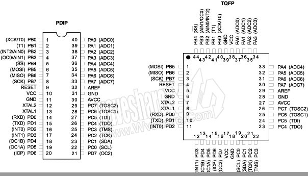
If you are a beginner and going through my datasheet for the first time, you won’t understand much and it is OK. Just have a look at my pinout diagram. You will see that most of the pins are named like this: PXY where X=A,B,C,D and Y=0 to 7. These are known as the I/O pins of the microcontroller. The other pins Vcc, GND, Reset, XTAL1, XTAL2, AVcc, AREF. You don’t need to care about the last four as of now. As for Vcc, that’s my mouth. If you want me to survive, you have to feed me. Just feed me a 5 Volt supply and a bit of current and I will be your genie! The GND pin SHOULD be connected to the circuit ground for best results.
I will now tell you about my various parts..err..ports.As for the PXY pins – I have 4 ‘ports’ – A,B,C and D (These will replace X). Each port has 8 pins – 0 to 7 (These will replace Y).

But what does I/O mean? I belong to the digital civilization and I follow TTL logic. In simple terms, I can’t differentiate between 0.2 Volts and 0.9 Volts because both are same for me – LOW. Similarly, I can’t differentiate between 3.6 Volts and 4.9 Volts because both are same for me – HIGH.
Practically,
0 to 1.4 Volts – LOW
3.4 to 5 Volts – HIGH
My inputs and outputs are always either HIGH or LOW. If any input or output is outside these ranges, well, don’t trust me. It is not my specialty!

Basic I/O configuration:
As I mentioned, 4 ports * 8 pins each = 32 I/O pins. But how do you tell me which pin you want to use? You do it using three ‘registers’. A ‘register’, in very simple terms, is nothing but a ‘group’ of 8 bits serving a similar purpose, generally. And this ‘group’ is given a name so that you can use it in your program to convey your desire to me.
The I/O registers commonly used are:

DDRX – DDR stands for Data Direction Register. This allows you to configure your pin as Input or Output. Now let me show you how to configure. Writing the following instruction (given inside single quotes):
‘DDRA = 0b11001001;’ – binary representation of port or ‘DDRA = 0xC9;’ – hexadecimal representation of Port. (Note: The pin order is 0b76543210)
Means that you want to set the pins 7,6,3 and 0 of Port A i.e Pins PA7, PA6, PA3 and PA0 as Output pins and the other pins of Port A as Input. By default all my 32 I/O pins are configured as Input i.e DDRX = 0b00000000.

PORTX – When you want to write either HIGH or LOW to a pin, you have to use my PORTX register. There are two cases:

      1)      Pin configured as Output
Let us continue with the above configuration i.e. DDRA = 0b11001001. If you now write the instruction,
‘PORTA = 0b01000001;’
Focus only on Pins 7,6,3 and 0 which are configured as OUTPUT. A ‘0’ has been written to Pin 7 and 3 and a ‘1’ has been written to Pin 6 and 0. This means that if you connect your multimeter probes between Pin 7 and GND, the voltage will read ~0 Volts i.e. Pin 7 has been set to LOW. Same is the case with Pin 3. On the other hand, connection of probes between Pin 6 and GND results in a reading of ~5 Volts i.e. Pin 6 has been set to HIGH. Same is the case with Pin 0.

Basically, writing 1 to an OUTPUT pin sets it HIGH and writing 0 to an OUTPUT pin sets it LOW.
      
      2)      Pin configured as Input
Again, we will continue with the same pin configuration i.e. DDRA = 0b11001001. If you now write the instruction,
‘PORTA = 0b00100010;’
Focus only on pins 5,4,2,1 which are configured as INPUT. A ‘0’ has been written to Pin 4 and 2 and a ‘1’ has been written to Pin 5 and 3. There is something called a pull-up resistor. The function of this is to simply pull the potential of the pin to HIGH. And writing a ‘1’ to the input-configured pin enables this resistor. Writing a ‘0’ to an input-configured pin does not do so and hence the pin is said to be ‘floating’. This is an undesirable condition as it can pick up stray potentials from the surroundings or the breadboard and can lead to erroneous results which are hard to debug if you don’t know about this concept (Trust me!). So the good habit is to always pull HIGH an input-configured pin by writing ‘1’ to it. Or alternatively, ground the input-configured pin, when not in use.

PINX – This is the register that stores the current status of each and every pin. So, if you want to read a particular pin, say 4th pin of Port B, all you have to do is: 
      1) Write the following instruction: ‘char c = PINB;’ – This will transfer the contents of the 8 bit register PINB into the 8 bit character instance ‘c’.
      2) Since you want only the status of the 4th pin, perform a logical AND of ‘c’ with 0b00010000. What this will do is, it will clear all the bits except the 4th. If the 4th pin is HIGH, ANDing it with the above will give the result 0b00010000 (let us call it ‘g’) and 0b00000000 (let us call it ‘h’), if not. 
      3) Check the value of the ANDed result – if value is ‘g’, then the 4th pin was HIGH, if the value is ‘h’, the 4th pin was LOW.

NOTE: Some IDEs like Code Vision AVR also allow direct access of pins by commands like DDRB.1, PORTC.4, PINA.4 etc. which simplify my user’s life!

Coding:
Besides the knowledge of these registers for I/O, you also need to include some header files (if you are working in, say, AVR Studio). Code Vision AVR has a code wizard that performs all these formalities for you so that you can directly write your code!
Given below is a sample code for AVR Studio that shows you what all header files you should include and other things you need to initialize. Also the code includes the usage of a delay function (parameter in milliseconds) that introduces a delay in your program giving you time to observe your results. The result of burning this code into me will result in my pin PB0 going high and low alternatively at a 1 second interval.

#define F_CPU 1000000UL           // CPU counts from o to 999999 in 1 second!
#include <avr/io.h>
#include <util/delay.h>

int main()
{
DDRB = 0b00000001;
while(1)
    {
        PORTB = 0b00000000;
        _delay_ms(1000);          // the parameter is 1000 ms = 1 second
        PORTB = 0b00000001;
        _delay_ms(1000);
    }
}

Important links and references:
1) http://www.atmel.com/dyn/resources/prod_documents/doc2503.pdf - detailed datasheet with sample codes for each and every feature
2) http://iamsuhasm.wordpress.com/tutsproj/avr-gcc-tutorial/ - a very good I/O tutorial with graphics, but please note, there are mistakes in this tutorial
4) http://www.avrfreaks.net/ - THE BEST site to learn more about AVR microcontrollers and their features and tutorials and discussions and lots more!


Thank you for reading my post. I wish you luck and hope you are able to use me well for your robot!

Tuesday, June 14, 2011

Dukaan-e-datasheets


Hi all. I am back with a new post after an extremely refreshing trip and in this post I will be covering some very commonly used ICs and components in beginner and techfest level robotics. This is NOT an exhaustive list. It is just an indicative compilation. Also, along with the brief function and purpose of each IC, I have also provided the links to various datasheets. I hope you will benefit from this.

Common application: If you plan to use the AC power available through the commonly seen 3-point connections to power your robot/application, you will need a step-down transformer. These transformers are easily available at any electrical shop. After stepping down the 220 Volts to say, 25 Volts by using a suitable transformer, you need to rectify the AC voltage to get DC voltage. Diodes are used for this purpose. This schematic shows how it is done.
The question that immediately comes to mind is, why do I need a transformer? Why not directly use the diodes for rectification? The answer lies in the datasheet, which states that the peak reverse voltage across the diode should not exceed 100 Volts. Practically, it should not exceed 60-70 Volts. Now again you will ask, why not use a diode of a higher rating? Well, they are costly and bulky. So, peace out.
   
Common application: Suppose you have managed to somehow get a DC power source- either using the transformer-rectifier circuit or some other source- but you can’t use this source directly because your components requirements, what do you do? Use a voltage regulator. The 78XX series is the most popular series of voltage regulators. These are 3-pin ICs having Input, Common and Output pins. The standard values to which you can bring down the DC voltages is 5,6,8,9,10,12,15 and 24 Volts. The maximum input values for all but 24 Volts regulation is 35 Volts whereas for 24 Volts regulation the maximum input is 40 Volts. Practically, the values should not exceed 30 Volts. Also, note that to achieve regulation, the minimum input should be at least 2 Volts higher than the regulated value. Therefore, to achieve 5 Volts regulation using IC 7805, the input should be at least 7 Volts.

Common application: So you have a problem statement at hand that requires you to measure the temperature and make the robot act accordingly. Here is your solution: AD590 is a temperature transducer IC whose output is a current proportional to the temperature. The output relation is linear with a change of 1uA/K. This output is converted into a voltage by connecting a resistor in series and measuring the potential drop across the resistor. The typical range of input voltage is 5-25 Volts (Maximum: 30 Volts).

Common Application: Don’t have an AD590? Go for this IC then! LM 35 has a linear increase factor of 10 mV/deg C. What’s more? LM35 is cheaper than AD590. But for applications that involve sending temperature measurement data across longer distances, AD590 is better as in LM35, the circuit will suffer from potential drop across the connecting wires.

Common Application: Need to acquire a signal in which noise is the more dominant signal (body signals or voice recognition in a crowded surrounding, for instance)? AD620 is an instrumentation amplifier IC and is a very popular choice among robotics enthusiasts. Very high gain is possible without significant loss in linearity. Supply voltage range is 5 Volts to 18 Volts.

Common application: Enjoy the tilt-based games in your smartphone? Awed by the sheer intelligence of a self balancing vehicle? Here lies the trick! Accelerometer ICs like ADXL330 measure the tilt of the IC in all three axes and provide an analog output proportional to the amount of tilt. Interfacing a sensor to a controller is a tough task and accelerometers are among the toughest to work with. But is sure is fun when you see your interface working successfully J

Common application: This is also an accelerometer IC that provides a digital output corresponding to the tilt. This digital IC is interfaced to the controller using I2C protocol (huh?). More on this later.


Common application: I have already discussed this motor driver IC in a previous post. Check it out.

Common application: Light dependent resistors are a very important class of photodetectors. The resistance of LDRs increases as the luminous intensity decreases and vice versa. One of the disadvantages associated with LDRs is the low speed of response called memory effect. But, a beginner should definitely take its interfacing up as a project.

Common application: LEDs have been used as indicators for a long time now and will be continued to do so for ages. Generally the potential drop across an LED is 1.7-1.8 Volts. The ideal connection involves a resistor in series with the LED so as to limit the current to a value around 10-15 mA. The maximum tolerable current is 30 mA but operation at this current for long reduces the life span of the LED. As we say, LED ‘phook jaayegi’. Going through the datasheet of an LED is suggested.

Common application: Making a line follower or a micromouse? Or working on a project that involves control based on digital input from various sensors? This is the IC to go for. LM324 has 4 comparators that can help you achieve discretization of your analog output. Or simply, switch between ON and OFF states based on value of input.  

Common application: Yes, this is the universal IC. Yes, this IC needs no introduction. Yes, this IC can’t take less than 12 Volts bi-polar supply. Yes, the source and sinking current is restricted to a maximum of 40 mA. Its applications are unlimited. It can be used in designing controllers, filters, comparators etc.

Hope this will help you find your datasheets whenever you need one :) 

Tuesday, May 24, 2011

Driving Circuits for DC motors

For a first timer, the rotation of a motor’s shaft, at just a push of a button, is pure thrill! Especially,if he has designed the circuit himself. This post is dedicated to DC motors, their driving circuits and ends with a sample DIY (do it yourself) breadboard circuit.

DC motor

The typical DC motor used in robotics is a 2 wired object having a shaft at its end.  

Typical ratings of DC motors commonly used are given in terms of ‘maximum supply voltage’ for stable operation and no-load speed expressed in ‘rpm’ (revolutions per minute). These motors are generally internally geared to provide increased torque to carry the weight of the robot and the circuitry and the ‘payload’ if any. Another important property of DC motors is that they are current-intensive components. Hence, ‘turning a motor on’ draws a large amount of current  suddenly from the power source.

For more theory on DC motors and their functioning, this is a very good starting point. 

Reversing the polarity of input voltage reverses the direction of rotation of the shaft (WOAH!! REALLY ?!). Also, it is a good practice to be aware of the absolute maximum ratings of your DC motor before using it as they vary from motor to motor.

DC motor driving circuits

1) H bridge circuits: Directional control is achieved by a hardwired circuit with the help of switches. This type of circuit is an example of pure hardware based control. The following diagram illustrates the directional control of a single DC motor using such a circuit.


Disadvantage of such a circuit is that wiring becomes highly complicated by the addition of a single motor to an existing circuit. Also, the switches undergo a lot of wear and tear as the switching action brings about a large change in potential (~12 V) and current (~400-500 mA - varies from motor to motor).

2) IC based circuits : The IC very commonly used for motor control is L293D. All ICs are accompanied by a ‘datasheet’ which all the details that you need to know before using that IC. You can download the datasheet of the L293D IC manufactured by ST Microelectronics here. The most important parts of this datasheet for us would be the pinout diagram (Page 2), the absolute maximum (Page 2) and the typical characteristics (Page 3). Following is the pinout diagram (from the datasheet) of L293D.


The functions of the various pins in simple terms are:

EnableX (X = 1,2) enables that side of the IC. Driving the EnableX pin high (~5 V generally) allows us to use the corresponding side (left or right) of the IC.

InputX (X = 1,2,3,4) is the control input for the IC. Driving InputX high drives the OutputX pins to Vs volts and driving it low (~0 V) makes the OutputX pin go low.

Vs is the voltage you want to apply to the DC motor connected across the output pins.

GND is the common or the reference potential of the circuit.

Vss is the control input for the IC that determines the minimum voltage that can be applied across the motor i.e. the minimum value of Vs.

We can achieve bi-directional control of two motors safely using this IC. For unidirectional control (not generally the case), we can use a single IC for 4 motors, but this is generally not done as a lot of current flows through the IC as all motors run simultaneously (the worst case), which might smoke it up – smoking is injurious for humans and ICs both!


DIY Breadboard schematic

Following bread-board schematic made using Fritzing Alpha illustrates the typical connection. Open the image in a new tab/window and have a close look at the connections.


Please note, in the above circuit, I have used a 5 V regulator IC (7805 or TO-220) to obtain 5V from 9V. All you need to know right now is that, with the named part of the IC facing you, the left most pin is the Input pin (Pin 1), the centre pin is the Common or the Ground (Pin 2) and the last pin is the Output 5 V pin (Pin 3). For proper functioning of this IC, the input voltage should be at least 2 V greater than the regulated voltage (5 V in this case). This diagram should make the connections clearer.
Also, the connections to the input have not been shown. They have to be done using switches between 5 V and GND potentials. Try it out yourself!


Cost breakup


DC Motor – Rs. 150-200
L293D IC – Rs. 60-80 

Hope this post was useful. Trust me, you will find yourself using the same circuit in almost all your motor-driving endeavours.
See ya!